Screw jack PO1 PO2 PO3 PO5 PSO1 PSO2 13 Assembly drawings. KEY S AND COTTER JOINT KEY-A piece of mild steel inserted between shaft and hub of mating member in axial direction.

Assembly Of Sleeve And Cotter Joint Engineering Drawing Engineering And Poetry Youtube
Indicate the important assembly dimensions and write the item list.

. Chapter 12 Assembly Drawings Universiti Teknologi Malaysia. Draw the required left hand side of cotter joint draw the cotter portion by using rectangle command Remove the sharp edges bu chamfer command Draw the shaft by using rectangle command and draw the sleeve by using rectangle command Draw arc for the sleeve by using arc command Click hatch command angle 45 degrees line to line distance 2mm. Exit the CAD software.
Meshing of cotter joint using ANSYS R15. Create a main assembly by taking a cental disc as main part. Log off the system.
COMPUTER AIDED MACHINE DRAWING 18ME36 KNUCKLE JOINT Draw the following views an assembled knuckle joint to 11 scale assuming the diameter of the rods d 20mm. Which are subjected to axial tensile or compressive forces. RESULT Thus the 3D assembly of the knuckle joint has been created on the software CATIA V5 with accurate dimension and with all respects.
Create a sub assembly using shaft and key using coincidence mates. A gib and cotter joint is usually used in strap end or big end of a connecting rod as shown in Fig. Edit and save if necessary.
11 Assembly drawings. THE WORKPIECE TO IMPART THE CLAP SWITCH WIKIPEDIA KNUCKLE JOINT ASSEMBLY DRAWING PDFKnuckle Joint Mechanical Wikipedia May 13th 2018 - A Knuckle Joint Is A Mechanical Joint Used To. Types of gear pdf gib and cotter joint socket and spigot joint classification of brakes types of fire in hindi application of cotter joint different types of brakes and their applications type of fire in hindi arduino projects ideas mechanical drill knuckle joint application application of knuckle joint type of gear difference between cotter joint and knuckle joint socket and.
CAD Model of cotter joint assembly. KEY COTTER AND KNUCKLE JOINTS SlideShare. Difference between cotter joint and knuckle joint pdf of two Following are the three commonly used cotter joints to connect two rods by a cotter.
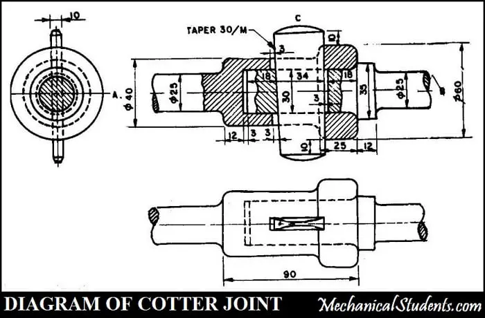
Front view with top half in section 2. One of the rods is formed into a socket by enlarging its end while the other rod called spigot end is formed with enlarged diameter and an integral collar The spigot is put inside the socket and the cotter is driven through the slots in socket and spigot ends. Two square rods of side 50 mm each are connected by a cotter joint with a gib.
Up to 24 cash back Open the assembly part then open the all parts one by one. Of a cotter joint with socket and spigot ends to connect two rods of 30 mm diameter each. Design of cotter joint.
1231 Design Assembly Drawing When a machine is designed an assembly drawing or a design layout is first drawn to clearly visualise the performance shape and clearances of various parts comprising the machine. Create a new drawing file. See All Design To Learn to Design and assemble The Parts i.
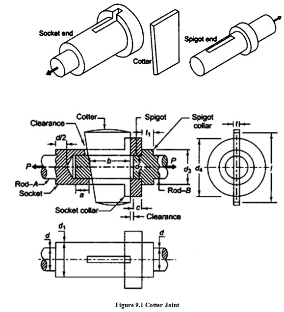
Cotter Joint has mainly three components spigot socket and cotter as shown in Figure 91. A cotter joint is a temporary fastening and is used to connect rigidly two co -axial rods or bars. Cotter joint is widely used to connect the piston rod and crosshead of a steam engine as a joint between the piston rod and the tailor pump rod foundation bolt etc.
Cotter Joint for Circular rods Socket and spigot. This PDF contains 500 detailed drawings of miscellaneous parts to be used for practice with AutoCAD or any 3D CAD package for that matter. 22 Assembly and Sleeve and Cotter Joint 67 23 Assembly of Gib Cotter joint 69 24 Assembly of Knuckle Joint 71 25 Assembly of Strap Joint 73 26 Assembly of Plummer Block 75 27.
A view from the eye end of the rod. Socket and spigot cotter joint is used to connect circular rods. Keys Cotter and 55 COTTER AND COTTER JOINT Knuckle Joints A cotter is a metallic strip of uniform thickness but tapers in width.
The locking device may be. This content and associated text is in no way sponsored by or affiliated with any company organization or real-world good that it. This is the complete explanation of the Design Procedure for Cotter Joint and Knuckle Joint which is shown in a detailed manner.
Has a head section and the other end is tapered along with a hole on its surface for the insertion of Taper pin after assembly as shown in the above figure. The cotter joint is withstanding the load applied during the working condition or not. The Assembly and disassembly of Cotter Joint are quicker.
1232 Detailed Assembly Drawing It is usually made for simple machines comprising of a relatively smaller number of simple parts. Elemental analysis at various loads. Assembly drawing of stuffing box crosses head of steam engine eccentrics piston and connecting rod.
Machine vice and tailstock PO1 PO2 PO3 PO5 PSO1 PSO2 14 Assembly drawings Rams-bottom Safety Valve feed check valve PO1 PO2 PO3 PO5 PSO1 PSO2. Autocad 3D Machine Drawing Assembly Learn In easy Way. Spigot is formed on one of the rods and socket is formed on the other.
Training Video For professional Designer. CONTENTS ASSEMBLY DRAWING Sleeve Cotter Joint 02 Socket Spigot Cotter Joint 06 Adjustable Joint 10 Gib Cotter Joint 14 Knuckle Joint 18 Flange Coupling 22 Protected Type Flange Coupling 26 Universal Coupling 30 Bushed Bearing 34 Plummer Block 38 Foot Step Bearing 43 Swivel Bearing 47 Simple Eccentric 53 Cross Head 58 Machine Vice 62 Screw Jack. A good assembly drawing should satisfy- 1.
The cotter passes through slots made in two coaxial parts and thus prevent the relative motion between them. To prepare assembly drawings both manually and using standard CAD packages. ASSEMBLY DRAWING The drawing which gives complete information of the object as a whole is called assembly drawing.
The Drawing of Knuckle joint in the. 100 but may be as large as 1. PO1 7 following views of the assembly.
Assemble flanges to the central disc and insert sub assembly of shaft and key to flanges. In such cases when the cotter alone ie. Insert the assembly into drawing and project the side view and front view.
P So the methodology of the study includes 1. Some of the parts are a bit more challenging than others but none of them are meant to be difficult. CAD Model of cotter joint using CATIAV5R20.
The CAD files and renderings posted to this website are created uploaded and managed by third-party community members. The taper may be very small like 1. Ball Joint Tool eBay.
Without gib is driven the friction between its ends and the inside of the slots in the strap tends to cause the sides of the strap to spring open or spread outwards as shown dotted in Fig. Connecting rod and eccentric PO1 PO2 PO3 PO5 PSO1 PSO2 12 Assembly drawings. However some are intended for specific modeling tools and hints have been provided in those cases.
Assemble the parts by using the tools. The remaining part for the design procedure of a cotter joint is presented in the form of a video which is shown below.

Machine Drawing Sleeve And Cotter Joint Socket And Spigot Joint And Knuckle Joint Autocad Isometric Drawing Gear Drawing Technical Drawing

Cotter Joint With Drawing Sheet 3d Cad Model Library Grabcad

Machine Drawing Btau305 Sunil Pipleya
Machine Drawing Sleeve And Cotter Joint Socket And Spigot Joint And Knuckle Joint
Design Procedure For Knuckle Joint Cotter Joint Formulas Pdf

Machine Drawing Sleeve And Cotter Joint Socket And Spigot Joint And Knuckle Joint Joint Autocad Autocad Drawing
Machine Design Lesson 9 Design Of Cotter Joint

31 Cotter Joint Final Pdf Computer Aided Design Autodesk
0 comments
Post a Comment